Introduction to GFRP Rebar for Concrete Reinforcement
GFRP rebar concrete reinforcement has emerged as a transformative alternative to traditional steel reinforcement in structural engineering. By replacing steel with Glass Fiber Reinforced Polymer (GFRP) bars, engineers can eliminate corrosion-induced degradation — the leading cause of premature failure in concrete structures worldwide. This comprehensive design guide provides structural engineers, specifiers, and contractors with everything they need to specify and design GFRP rebar concrete reinforcement systems, covering material properties, code requirements, installation practices, and application-specific considerations.
Unlike conventional steel reinforcement, GFRP rebar is inherently immune to chloride attack and chemical corrosion. This makes it particularly valuable in environments where concrete structures are exposed to deicing salts, marine conditions, wastewater, or aggressive soil chemistry. The following sections examine the material characteristics, design methodology, and practical considerations for implementing GFRP rebar concrete reinforcement in modern structural engineering projects.
What Is GFRP Rebar for Concrete Reinforcement?
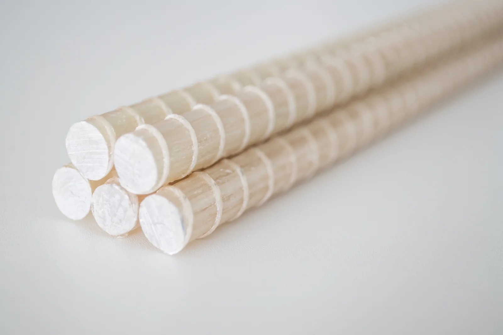
GFRP rebar for concrete reinforcement is a composite reinforcing bar manufactured from high-strength glass fibers embedded in a vinyl ester or epoxy resin matrix. Unlike traditional steel reinforcement, which relies on ductility and yield strength, GFRP rebar provides linear-elastic behavior up to failure, with high tensile strength and no yield point. This fundamental difference requires engineers to adopt distinct design philosophies when specifying FRP reinforcing bar for concrete structures.
The manufacturing process — pultrusion — aligns continuous glass fibers longitudinally through a resin bath and heated die, producing a bar with exceptional axial tensile strength. The surface is typically coated with a sand layer or deformed with helical wraps to ensure adequate bond with surrounding concrete. Standard diameters range from 6 mm to 32 mm, with tensile strengths typically between 600 MPa and 1,200 MPa depending on bar size and fiber volume fraction.
Key characteristics that define GFRP rebar concrete reinforcement include:
- Corrosion immunity: GFRP does not rust or oxidize, eliminating spalling and delamination caused by steel expansion
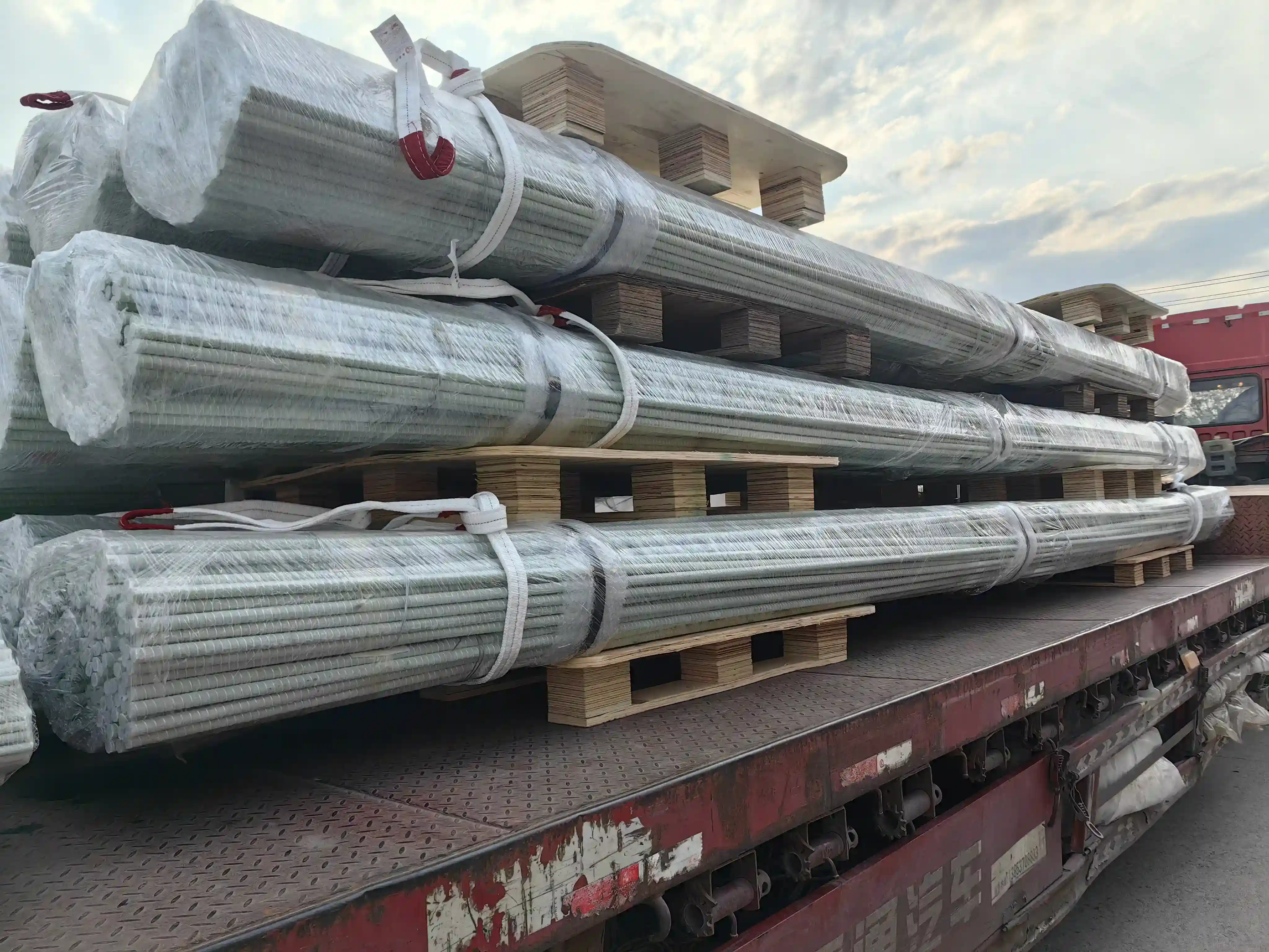
- High strength-to-weight ratio: Approximately one-quarter the weight of steel rebar, reducing transportation and handling costs
- Electromagnetic neutrality: Non-conductive and non-magnetic, ideal for sensitive infrastructure like MRI facilities and electrical substations
- Thermal compatibility: Similar coefficient of thermal expansion to concrete, minimizing differential stress at the bond interface
GFRP rebar is used in a wide range of concrete reinforcement scenarios, including bridge decks, sea walls, tunnel linings, parking structures, chemical plants, and coastal infrastructure where corrosion resistance is critical.
GFRP Rebar vs. Steel Rebar in Concrete
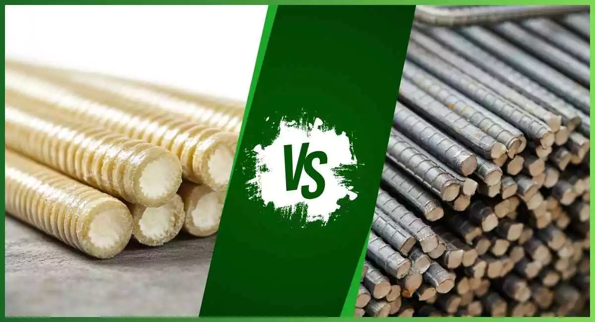
Understanding the differences between GFRP and steel is essential for structural engineers evaluating GFRP rebar for concrete reinforcement. Each material has distinct mechanical behaviors that influence design decisions.
| Property | GFRP Rebar | Steel Rebar |
|---|---|---|
| Tensile Strength | 600 – 1,200 MPa | 400 – 620 MPa (Grade 60/80) |
| Yield Point | None (linear-elastic to failure) | Clear yield plateau |
| Modulus of Elasticity | 40 – 60 GPa | 200 GPa |
| Elongation at Break | 1.5 – 2.5% | 8 – 14% |
| Density | 1.9 – 2.2 g/cm³ | 7.85 g/cm³ |
| Corrosion Resistance | Excellent (immune to chlorides) | Poor (rusts in presence of chlorides) |
| Thermal Conductivity | Low (0.3 – 0.5 W/mK) | High (50 – 60 W/mK) |
| Electrical Conductivity | Non-conductive | Conductive |
The primary advantage of GFRP rebar over steel in concrete is its complete resistance to chloride-induced corrosion. In steel-reinforced concrete, chloride ions penetrating the cover layer depassivate the steel, initiating expansive rust that cracks and spalls the concrete. GFRP eliminates this failure mode entirely, enabling thinner concrete cover, reduced maintenance, and service lives exceeding 100 years in aggressive environments.
However, GFRP’s lower modulus of elasticity means that crack widths and deflections are typically larger than in equivalent steel-reinforced sections. Engineers must compensate through increased reinforcement ratios or deeper sections. The linear-elastic behavior also means no ductility warning before failure — a consideration addressed through strength design factors in ACI 440.11.
Mechanical Properties of GFRP Rebar for Concrete Reinforcement
Accurate mechanical property characterization is the foundation of safe GFRP rebar for concrete reinforcement design. Unlike steel, which has standardized yield strengths across grades, GFRP mechanical properties vary by manufacturer, fiber type, resin system, and bar diameter.
GFRP Rebar Tensile Strength for Concrete Reinforcement
The GFRP rebar tensile strength for concrete reinforcement is the primary design parameter. GFRP bars exhibit tensile strengths ranging from 600 MPa to 1,200 MPa, significantly exceeding Grade 60 steel’s 420 MPa yield strength. However, because GFRP does not yield, the design tensile strength is calculated using an environmental reduction factor (CE) per ACI 440.11, which accounts for long-term durability under service conditions:
- CE = 0.90 for dry interior exposure (buildings)
- CE = 0.80 for exterior exposure (bridges, parking structures)
- CE = 0.70 for aggressive environments (seawater, chemical exposure)
Design tensile strength ffu = CE × f*fu, where f*fu is the guaranteed tensile strength (mean minus three standard deviations). Typical guaranteed strengths are 750 – 900 MPa for standard bars. This conservative approach ensures reliable performance over the structure’s design life.
GFRP Rebar Shear Strength Considerations
GFRP rebar shear strength is significantly lower than steel due to the anisotropic nature of fiber-reinforced polymers. While longitudinal fibers carry axial tension efficiently, transverse shear is resisted primarily by the resin matrix and fiber-matrix interface. The shear strength of GFRP rebar is typically 150 – 250 MPa, approximately 20–30% of its tensile strength.
In structural design, this has several implications:
- Shear stirrups must be designed with larger diameters or closer spacing than equivalent steel stirrups
- Bent bars and hooks must have minimum bend radii (typically 4–6× bar diameter) to avoid fiber rupture at the bend
- Development length calculations account for the lower transverse strength through increased embedment lengths
- ACI 440.11 limits shear stress in GFRP reinforcement to prevent premature shear failure at bends
Designers should also note that GFRP’s modulus of elasticity (40–60 GPa) is about one-third of steel’s, making serviceability (deflection and crack control) the governing criterion in many concrete reinforcement designs.
GFRP Rebar Concrete Reinforcement Design Guidelines
Structural engineers designing with GFRP rebar for concrete reinforcement must follow specific code provisions that account for the material’s unique behavior. The primary design standard is ACI 440.11-22, “Building Code Requirements for Structural Concrete Reinforced with GFRP Bars.”
Design Principles per ACI 440.11
ACI 440.11 establishes GFRP rebar concrete reinforcement design guidelines that differ substantially from steel reinforcement design. Key principles include:
- Strength design method: Similar to steel design in philosophy but with different strength reduction factors (φ factors). For GFRP-reinforced sections, φ = 0.55 for tension-controlled sections and φ = 0.65 for compression-controlled sections
- Over-reinforcement requirement: Sections must be designed as over-reinforced (concrete crushing before GFRP rupture) because GFRP lacks ductility. This ensures compressive failure of concrete provides some warning before collapse
- Serviceability-first approach: Deflection and crack width limits often govern the design because GFRP’s lower modulus produces larger deformations under service loads
- Development and splicing: Longer embedment lengths are required — typical development lengths are 40–60 times bar diameter, compared to 20–30 diameters for steel
- Minimum reinforcement ratio: A minimum of 1.4/ffu (in MPa) to prevent brittle failure at first cracking
ACI 440.11 also addresses specific design checks including flexural strength, shear capacity, crack control (maximum crack width of 0.5 mm for exterior and 0.7 mm for interior exposure), deflection limits, and creep-rupture endurance. The code limits sustained service stress in GFRP to 0.20 ffu for creep-rupture and 0.30 ffu for fatigue considerations.
These GFRP rebar concrete reinforcement design guidelines ensure that structures maintain safety and serviceability throughout their intended service life, even in aggressive environments where steel reinforcement would rapidly deteriorate.
How to Use GFRP Rebar for Concrete Reinforcement in Slabs
One of the most common applications for GFRP rebar for concrete reinforcement is in slab construction. Parking structures, bridge decks, industrial floors, and residential foundations all benefit from the corrosion resistance and durability of GFRP reinforcement.
When designing concrete slabs with GFRP rebar, engineers follow a serviceability-controlled process:
- Determine service loads and calculate expected moments and shears
- Select trial reinforcement based on strength requirements per ACI 440.11
- Check deflection using effective moment of inertia (Ie) formulas modified for GFRP’s lower modulus
- Verify crack width using the GFRP-specific crack width equation that accounts for bond characteristics
- Confirm development length at all critical sections and support points
For two-way slabs, the same design procedure applies, but the reinforcement spacing must account for GFRP’s lower stiffness. Typical spacing ranges from 150 mm to 300 mm, with the closer spacing used in higher-load areas. The minimum clear spacing between parallel GFRP bars should not be less than the bar diameter or 25 mm, whichever is greater.
GFRP Rebar Installation Guide for Concrete Structures
Proper installation is critical to achieving the design performance of GFRP-reinforced concrete. Follow this GFRP rebar installation guide for best results:
- Handling and cutting: GFRP bars can be cut on-site using a diamond-blade saw or abrasive cutoff wheel. Never use a torch — GFRP does not melt like steel and will char at high temperatures
- Support and tying: Use plastic or stainless steel tie wires. GFRP is lightweight (1/4 the weight of steel), so fewer supports are needed. Space supports at 1.0–1.5 m intervals
- Bending: GFRP rebar cannot be cold-bent on site. All bends, hooks, and stirrups must be prefabricated by the manufacturer. Minimum bend diameters follow ACI 440.11: 4× bar diameter for stirrups, 6× for main bars
- Placement: Position GFRP bars accurately using bar chairs. The sand-coated surface provides excellent bond but can be abrasive — wear gloves during handling
- Concrete placement: Use vibration carefully. GFRP’s lightweight can cause displacement if concrete is placed too aggressively. Use concrete with maximum aggregate size not exceeding 1.3 times the clear spacing between bars
Following these guidelines ensures that the GFRP reinforcement achieves the intended bond strength and structural performance throughout the concrete member’s service life.
Applications of FRP Reinforcing Bar for Concrete Structures
FRP reinforcing bar for concrete has proven successful across a wide range of structural applications. While no single reinforcement material is optimal for every scenario, GFRP excels in environments where corrosion poses a structural risk.
Is GFRP rebar suitable for all types of concrete structures? Not all. GFRP is best suited for structures where corrosion resistance, electromagnetic neutrality, or weight reduction provides a clear advantage. It is less suitable for applications requiring high ductility or where fire resistance without adequate cover is a concern (GFRP retains approximately 70% of strength at 200°C but degrades above 350°C).
| Structure Type | Suitability | Primary Benefit |
|---|---|---|
| Bridge decks | Excellent | Corrosion resistance from deicing salts |
| Seawalls and marine structures | Excellent | Complete immunity to saltwater corrosion |
| Parking garages | Excellent | Resistance to chloride penetration from vehicles |
| Chemical processing plants | Excellent | Resistance to aggressive chemical exposure |
| MRI and medical facilities | Excellent | Non-magnetic properties |
| Tunnel linings | Good | Corrosion resistance in groundwater |
| Residential foundations | Good | Long-term durability in aggressive soils |
| High-rise columns (gravity) | Limited | Ductility concerns; hybrid reinforcement recommended |
| Seismic moment frames | Limited | Low ductility; special detailing required per ACI 440.11 |
The selection of GFRP should always be based on a life-cycle cost analysis that accounts for initial material cost, installation savings (lighter weight, fewer crane lifts), reduced maintenance, and extended service life. In aggressive environments, GFRP-reinforced concrete structures typically achieve lower total ownership costs despite higher initial material prices.
Conclusion: The Future of Concrete Reinforcement with GFRP Rebar
GFRP rebar for concrete reinforcement represents a paradigm shift in structural engineering — moving from a corrosion-dependent maintenance model to a durable, long-service-life approach. As ACI 440.11 continues to gain adoption and more manufacturers achieve ASTM D7957 certification, the barriers to specifying GFRP rebar continue to fall.
For structural engineers, the key takeaways are:
- GFRP rebar eliminates corrosion as a failure mode, enabling 75–100 year design lives in aggressive environments
- Design must follow ACI 440.11 provisions, with emphasis on serviceability limits and over-reinforcement requirements
- The GFRP rebar tensile strength and GFRP rebar shear strength differ fundamentally from steel; design values must incorporate appropriate environmental reduction factors
- FRP reinforcing bar for concrete is most cost-effective in corrosion-prone structures, where life-cycle savings offset initial material costs
- Proper installation practices, including prefabricated bends and careful concrete placement, ensure the reinforcement performs as designed
To learn more about how GFRP rebar can enhance your next concrete reinforcement project, contact our engineering support team for project-specific design assistance and material specifications.